Demystifying the MAX30102: How This Tiny Biometric Sensor Tracks Your Pulse and SpO2
Ever wondered how smartwatches and fitness trackers read your pulse through your skin? It feels like magic, but it is actually a clever combination of optical physics, fluid dynamics, and embedded engineering.
One of the most popular, accessible tools for bringing this technology into your own DIY projects is the MAX30102 sensor—frequently found on the low-cost MH-ET Live breakout board. Whether you are building an IoT health dashboard, a smart companion robot, or an embedded diagnostic tool, this guide breaks down exactly how the hardware works, how to navigate a notorious hardware pitfall, and how to wire it up to an ESP32 to stream real-time biometric data.
The Core Physics: What is Photplethysmography?
At the heart of the MAX30102 is a technique called Photplethysmography (PPG). Stripping away the medical jargon, PPG is simply the practice of shining light into living tissue and measuring how much of that light is absorbed by your blood vessels.
Every time your heart beats, a pressure wave forces oxygen-rich blood through your body, causing the tiny capillaries in your fingertips or wrist to temporarily expand. In the split second between beats, that volume recedes. Because blood absorbs light differently than bones or skin tissue, we can trace your cardiac cycle by watching the variations in reflected light.
Anatomy of the MAX30102 Hardware
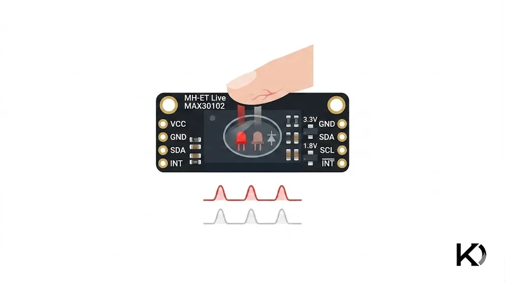
If you look closely at the tiny black integrated circuit (IC) in the middle of the MH-ET Live breakout board, you will spot a specialized glass window divided into two distinct chambers:
- The Emitters (Two LEDs): The chip contains a Red LED (generating a 660nm wavelength) and an Infrared (IR) LED (generating an 880nm wavelength).
- The Detector: A highly sensitive photodiode sits in the adjacent chamber, isolated from the LEDs by an internal wall to prevent light from bleeding across directly without hitting your skin first.
1. Tracking Heart Rate (BPM)
To calculate your Beats Per Minute (BPM), the sensor primarily relies on the Infrared LED. The chip floods your tissue with IR light. When a pulse wave rushes through your finger, the sudden surge in blood volume absorbs a large portion of that light, meaning less of it bounces back. Between beats, absorption drops, and more light reflects back into the photodiode.
The photodiode converts these moving light levels into a continuous electrical signal, creating a classic waveform. By measuring the time intervals between the peaks of this wave, the software calculates your heart rate.
2. Measuring Blood Oxygen ()
Determining your oxygen saturation levels requires both the Red and IR LEDs working in tandem. This relies on a fascinating biological quirk of hemoglobin (the iron-based protein in your red blood cells):
- Oxygenated Hemoglobin (): Absorbs more Infrared light and allows more Red light to pass through or reflect.
- Deoxygenated Hemoglobin (): Absorbs more Red light and allows more Infrared light to pass through or reflect.
The MAX30102 rapidly flashes the Red and IR LEDs alternately at hundreds of times per second. By evaluating the ratio of the reflected light from both states, it calculates a value known as the Ratio of Ratios ():
Hardware Detail: The AC component represents the dynamic, pulsating blood flow tied to your heartbeat. The DC component represents the static elements—your bones, skin, and steady venous blood that absorb a constant amount of light. Isolating the AC component allows the sensor to ignore everything else and look strictly at your moving arterial blood.
The onboard circuitry automatically filters out external ambient room light, processes the signals through an internal 18-bit Analog-to-Digital Converter (ADC), and passes the clean digital data out over an communication bus via standard Data (SDA) and Clock (SCL) lines.

Hardware Gotcha: The MH-ET Live Design Flaw
Before jumping into wiring, there is a vital hardware detail every developer using the MH-ET Live variant should know.
The MAX30102 chip requires a 1.8V power rail internally, but the breakout board includes onboard regulators so it can accept 5V or 3.3V. However, the designers tied the onboard pull-up resistors directly to the 5V (VIN) rail by default.
If you hook this board up to a 3.3V microcontroller—like an ESP32 or an STM32—the 5V pull-ups can flood your controller's pins with a higher voltage than they are designed to handle. This frequently manifests as sudden bus lockups, or the sensor refusing to initialize entirely.
The Fix: If you experience connection drops, look for the tiny trace on the back of the PCB connecting the pull-up array to the 5V pad. Cutting that trace with an exacto knife and soldering a small jumper bridge over to the 3.3V pad forces the pull-ups to operate on safe, microcontroller-friendly logic levels.
Step-by-Step Integration: ESP32 & Arduino Guide
Let's look at how to pull raw optical data straight from the sensor using an ESP32 and the Arduino IDE.
1. The Hardware Connections
Standard ESP32 development boards default to GPIO 21 for SDA and GPIO 22 for SCL. Wire up your components according to the layout below:
| MH-ET Live Breakout Pin | ESP32 Target Pin | Wire Purpose |
|---|---|---|
| VIN | 5V / VIN | Powers the onboard LEDs |
| SDA | GPIO 21 | Serial Data |
| SCL | GPIO 22 | Serial Clock |
| GND | GND | Ground Reference |
Note: The INT (Interrupt) pin is useful for advanced power-saving sleep modes, but you can leave it disconnected for standard, real-time data streaming.
2. Software Installation
Open your Arduino IDE, navigate to Sketch -> Include Library -> Manage Libraries..., search for "SparkFun MAX3010x", and install the latest version. This library was written for the MAX30105 but is completely backward-compatible with the MAX30102 registers.
3. The Firmware
Upload this script to your ESP32. It initializes the bus at full speed, configures the internal LED drivers, and loops through the FIFO buffer to output the raw red and infrared values.
#include <Wire.h>
#include "MAX30105.h"

MAX30105 particleSensor;

void setup() {
  Serial.begin(115200);
  Serial.println("Initializing MAX30102...");

  // Fire up standard I2C (Pins 21 and 22 on standard ESP32 boards)
  Wire.begin();

  // Validate sensor communication
  if (!particleSensor.begin(Wire, I2C_SPEED_FAST)) {
    Serial.println("Sensor not found. Verify your wiring, power, and I2C pull-ups.");
    while (1);
  }

  // Define tailored register configurations
  byte ledBrightness = 60; // 0 (Off) to 255 (50mA). 60 provides ~12mA of drive current.
  byte sampleAverage = 4;   // Smooths signal by averaging samples (Options: 1, 2, 4, 8, 16, 32)
  byte ledMode = 2;         // 1 = Red Only (BPM), 2 = Red + IR ($SpO_2$), 3 = Multi-LED
  byte sampleRate = 100;    // Standard Hz sampling rate (Options: 50, 100, 200, 400, up to 3200)
  int pulseWidth = 411;     // Controls LED on-time in microseconds (69, 118, 215, 411)
  int adcRange = 4096;      // ADC full-scale range configuration (2048, 4096, 8192, 16384)

  particleSensor.setup(ledBrightness, sampleAverage, ledMode, sampleRate, pulseWidth, adcRange);
}

void loop() {
  // Grab the latest unrefined photodiode values from the sensor's FIFO stack
  uint32_t redValue = particleSensor.getRed();
  uint32_t irValue = particleSensor.getIR();

  // Threshold check: if no finger is touching the glass, values drop off drastically
  if (redValue < 50000) {
    Serial.println("Place your finger gently on the sensor.");
  } else {
    // Print using key-value structure readable by the Arduino Serial Plotter
    Serial.print("Red:");
    Serial.print(redValue);
    Serial.print(",");
    Serial.print("IR:");
    Serial.println(irValue);
  }

  delay(20); // 50Hz refresh rate cycle to match processing overhead
}
Visualizing the Results
Once uploaded, open your Arduino IDE Serial Plotter (Ctrl + Shift + L) and match your speed to 115200 baud.
Rest your finger flat and lightly against the glass window of the sensor. Within a couple of seconds, you will see two synchronized waves moving across your screen.
Pro-Tip for Clean Data: A common mistake is pressing down hard on the sensor out of habit. Pressing too firmly compresses the delicate blood vessels in your fingertip, blocking the local arterial pulse entirely. This flattens your waveforms into erratic static. For the cleanest signal, place your finger with just enough weight to seal out the ambient light of the room.
Kavishka Dulshan